#16 3D-Modelling the robot parts (Solidworks) - Matrix table
- Aurel

- Apr 18, 2022
- 3 min read
Updated: May 3, 2022
To start building the robot, first I need to do some sketches about the parts of the legs, and then make FEA simulation on each of them to determine their individual strength and resistance and put all results in a Matrix table. The will give me a starting point for the main design of the robot.
In order to start designing I made a list of components to have in mind clear what are the key ones:
bones (connectors for all joints) x4
main wheels x2 (working as "feet" for the robot): -dc motors with rotating shafts -hexagonal connectors that fit on the shafts and inside the actual wheels -wheels
knee joints x2: -stepper motors with rotating shafts -couplings for each motor (attached to "shoulder joints")
shoulder joints x2: -stepper motors with rotating shafts -couplings for each motor (attached to "head controller")
head controller/power x1: -IC (arduino size) -IMU -battery
I have started with the bones, where I have made a Matrix table to decide which shape would be best fit to hold to heavy parts of the robot and not break. In the Matrix table I have rated each component after each drawing had its respective part made in Solidworks and FEA simulation performed on it.
Solidworks doesn't have the PLA as a material, and since more parts would be 3D-printed from PLA I have decided to search for the properties and create a new material so I can use it for more realistic simulations:

Some of the sources I used to get those values are dispersed around internet as there is not 1 specific place I took all of them, but a starting point which led to other points was https://www.makeitfrom.com/material-properties/Polylactic-Acid-PLA-Polylactide .
I have made 5 quick sketches/designs for the bones and assigned to each one of the the PLA material. The hole on the left alongside with the extreme left side of the parts were all fixed points, meaning they couldn't move, then a force from the relative up towards the relative down was used, a force equal to 19.614 N (corresponding to 2 kg of assumed final weight of the robot in an environment where the gravity is equal to 9.807 m/s^2 ). The weight will ultimately be distributed on 2 legs, however the weight was still applied as a total to each of the components in the FEA simulation to test the worst case scenario (for example when the robot tips over to one of the sides, or collides with another object).

Individual FEA simulation tests have been performed on each, and the values found in the table are the maximums displayed in the below images, each prototype holds 2 images, first image always displaying the stress, made on the Von Misses scale, and second the displacement, made on the URES scale (resultant displacement):
Prototype 1:
Stress

Displacement

Prototype 2:
Stress

Displacement

Prototype 3:
Stress

Displacement

Prototype 4:
Stress

Displacement

Prototype 5:
Stress

Displacement

The matrix table containing labelled prototypes (from 1 to 5) where each has a different type of "bones" holding the robot up:
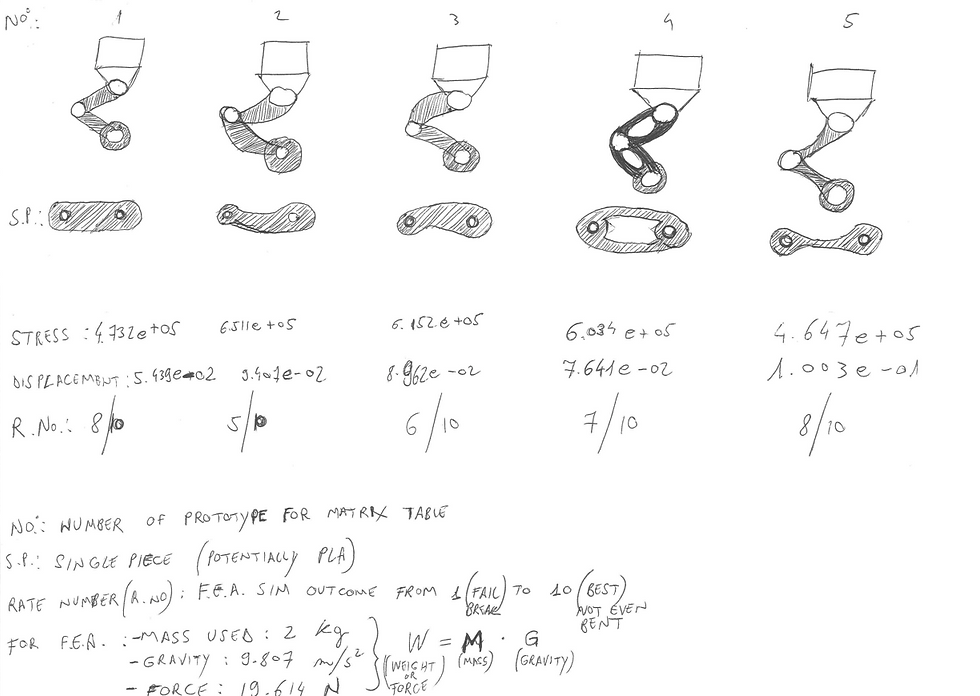
The Matrix table helped me decide to have a starting point, and do the no.5 as the best candidate for continuing the build. The interesting part of this for me was to discover why bones in nature look similar to that shape, and it is because it is by far the best performing when it comes to holding a weight on it while using less material. I also think that the no.5 will give the robot a more organic/natural look when fully assembled.
Next I will make all parts and assemble them together.


Comments