#4 Basic Self-balancing on 2 wheels (model and control)
- Aurel

- Feb 12, 2022
- 6 min read
Updated: May 5, 2022
I built a simple assembly made of 2 wheels with a shaft, and a chassis (made of 3 shelves and some rods). Physics have been tested and I attempted to achieve self-balancing through a PID controller. This system has been made following the guided model from: https://uk.mathworks.com/matlabcentral/fileexchange/88768-two-wheeled-self-balancing-robot
Building the system:
Following the previous assembly made in Simscape of a basic pendulum, I have built a 3-shelf chassis for a basic robot, and its 2 wheels with a shaft. They are simple solid blocks which are assembled to stay and stick to each other via "Rigid Transform" blocks, which constrain the pose of each object with respect/reference to another object or point.

Each wheel is being made into a subsystem to keep the final system simplified. And the wheels together with the shaft is a subsystem itself.

The same logic of building the cart of the robot, was applied to build the upper body with the 3 plates/shelves and the correspondant rods. (All this is made purely to have realistic yet simplified looks).
The subsytem containing the plates and the rods: all bodies are held together and moved by reference to the "Plate 1" block. This means that if "Plate 1" moves or rotatates, all other components will move together with respect to this particular block.
The "Rods - compound" subsystem contains 4 lines inside, each has a solid block + rigid transform + connection to outside of subsystem.
The "External force and Torque" illustrated in the figure below is just there to give an impulse push at the top of the "plate 3" in the Y axis direction (towards the relative "back" of the robot), just as a small disturbance; because without it, when simulation starts the robot would stay in an perfectly upright position because it is simmetric and the only constant force present is in X- direction (which is the DOWN in this simulation). This force is simply to bring realism in the simulated environment.
**World Orientation is discussed towards the end of this post.

The following table indicates each component's details:
Names | Sizes | Positions |
|---|---|---|
Tyre (left wheel) | Radius= 40mm Length = 20mm | -Z (on shaft)= 100 mm |
Body (left wheel | Radius = 30mm Length = 20.2mm | -Z (on shaft)= 100 mm |
Tyre (right wheel) | Radius= 40mm Length = 20mm | +Z (on shaft)= 100 mm |
Body (right wheel) | Radius = 30mm Length = 20.2mm | +Z (on shaft)= 100 mm |
Shaft | 10mm x 10mm x 200mm | centre of wheels and along the Plate 1's X axis |
Plate 1 | 180mm x 80mm x 3mm | rotated [Y-X-Z] - [90° 180° 0°] |
Plate 2 | 180mm x 80mm x 3mm | plate 1 - Z+ 100mm |
Plate 3 | 180mm x 80mm x 3mm | plate 1 - Z+ 250mm |
Rod 1 | Radius= 5mm Length = 250mm | plate 1 - [(180/2-1) (80/2-1) (-250/2)] |
Rod 2 | Radius= 5mm Length = 250mm | plate 1 - [(-180/2+1) (-80/2+1) (-250/2)] |
Rod 3 | Radius= 5mm Length = 250mm | plate 1 - [(180/2-1) (-80/2+1) (-250/2)] |
Rod 4 | Radius= 5mm Length = 250mm | plate 1 - [(-180/2+1) (80/2-1) (-250/2)] |
(Video below is with a full system built, but PID values of 0, and is used here only to reference the gravity and damping and how they affect my robot)
Moving forwad with the system, once this was achieved I have added a PID controller to make the system behave according to the following control loop model.
In this model, I want to take the Theta, which is the inclination angle between my system (the robot) and axes. Theta is being passed through an addition/subtraction point, that returns the error between the desired angle/setpoint (0° deg) and actual angle (theta). The errors then passes as an input through the PID controller, that provides the necessary force to be applied and balance the robot.

Follow through the guided example mentioned at the beginning of this post, I have built a model in a system that seems to be doing just that.
(The whole robot has a Rigid Transform with a rotation sequence of [90° 180° 0°] with respect to the axes X-Y-X of the world.)
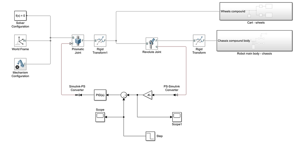
The essentials parts of this system are explained as follows:
In this model, to have a realistic simulation it was needed a Prismatic Joint which allows my system to move/translate inside the "world", the correspective "Rigid transform 1" makes sure that the whole robot can move assembled.
Then the next part required, it was a Revolute Joint which allows rotation of the between of the wheels with respect to the body. This block was put on the "chassis" subsytem of the robot because it allows to track the position, therefore the robot's inclination, whereas if this was put on the line of the "wheels" subsytem, it would track wheels inclination, much like an encoder would do of a motor and that would not be useful since the wheels must rotate to satisfy the chassis position not viceversa.
The block "K" (which is a gain block) allows me to convert from radiants to degrees, as the revolute joint would naturally provide radiants. Inside it has the formula of: "-180 / 3.14"
The Step block is to ensure that there is a push/impulse given to the system whenever is needed which, thanks to the next 2 blocks, the "summation" and the "PID", will get and stabilize if the inclination of the robot changes. It has a step time of 0.01 sec, an initial value of 10, then a final value of 0.
The PID block, is the most crucial one, as it does all the computation needed to give process the information and keep the system stabilized, if properly tuned.
Tests:
Before going straight into the PID block and hitting the "Tune" button I have decide to run several tests to ensure I understand better and visually what happens:
Test 1 - PID [ 3 0 0]:
The robot is trying to achieve a vertical stable stance, however it becomes very quickly unstable, which is also seen in the graph below.
Legend: graph has for vertical the angles and for horizontal the time in seconds.

Test 2 - PID [ 1 1 0 ]:
I have tried to reduce the Proportional value from 3 to 1, and change the Integral value from 0 to 1 to observe what behavior it would perform and this was the result, still unstable, just like before.
Legend: graph has for vertical the angles and for horizontal the time in seconds.

Test 3 - PID [ 1 0 0.01 ]:
In this case I have decided to not continue increasing the Integral value but rather keeping it to a null value while increasing very slightly the Derivative value, and the results seemed to be satisfying and showed a more desired outcome. Without the need for a graph I could see that this system is already stable with these values.
Test 4 - PID tuned automatically [ see bottom right part of graph below ]:
(Video Speed 8x slowed)
This time I have just let the "Tune" button do the job, and see what the outcome would be, and this is it, however I see that the robot stabilizes and moves in a direction, which isn't good.
The tuned PID also produced a graph which clearly shows that the time it takes to stabilize is very little, with minimal overshoot, but I don't like the fact that it moves towards one side:

Test 4 - PID [ reduced the Derivative value up until a quarter of its value] :
For this one I have tried to manually tune the values given by the automatically tuned values, in order to eliminate that side translation, and to keep it stable yet in one place. This is so far my best attempt.
As seen in the video and graph, it takes almost half of a second to fully stabilize.
Legend: graph has for vertical the angles and for horizontal the time in seconds.

These graphs with black background are taken from the "Scope 1" block.
EXTRA TEST:
Following my regular meeting with my Supervisor and Co-Supervisor, I have tried to solve that lateral movement by changing the impulse given to the robot and adding 2 step inputs and a nested sum, which improved the outcome, but still maintained that lateral movement. See below for testing:

The robot was still moving towards lateral side (this time in the opposite direction), and I have decided to apply the logic of first auto-tuning the PID then manually apply the same for the Derivative (the value divided by 4, like in my 4th test) and the results are as below:
Legend: graph has for vertical the angles and for horizontal the time in seconds.

The results are very similar, but in this it looks like it takes more than half a second to fully stabilize, so I will continue to work and keep the results found at "Test 4".
Conclusion:
For this task I believe I have successfully understood how to create a good amount of assembly and simulation inside the Simscape environment, test it and analyze it.
One of the things I could try to manipulate are the damping, since the first video isn't fully realistic when it comes to swinging the robot without PID. Perhaps doing that and playing more with the PID values manually I could perhaps try to keep the robot fully into place.
**Another issue is the orientation, I need to make that to a conventional one, since at the moment I have X+ as my "up", X- as my "down", then Z+ as "forward" and Z- as "back", but I would need to change this when I will do my main robot back to Z+ as "up", Z- as "down", X+ to "foward", X- as "back" , and so on.

Continuing with this same model which I have, I will need to try to sense and actuate the Torque and perhaps even Velocity of the wheels, in order to get an even more realistic approach and simulation rather than just "movement" and "position". I decided that I will keep this relatively simple build for all my future tests until I make it achieve self-balance through Torque.


Comments